[Schmetterlinge I]
![[Schmetterlinge I]](/content/images/size/w1200/2025/12/thumbnail2_1.6.2.png)
Schmetterlinge I is a kinetic new media installation featuring a swarm of vibrant butterflies interacting with their environment. Up close the wings showcase real-time generative textures while the movement of the wings create emergent patterns from a distance. This first iteration includes 48 custom-engineered, individually controllable butterflies, projection-mapped in sync with the movement of their wings.
Key Technologies: Projection Mapping, TouchDesigner, Microcontrollers, Servos, 3D Printing, Art-Net, GLSL

Powered by TouchDesigner, the system bridges the digital and physical worlds, driving both the projection mapping and movement of the servos.
This project was developed initially as an immersive backdrop for a concert I hosted in December. I wanted to create something that would push the limits of what was possible with my current resources. Inspired by the butterfly motif of the headliner Animat's Slowwalker EP, I challenged myself to create a swarm of projection mapped, animatronic butterflies.
The mechanism for the movement of the wings
In the following deep dive, I will break down the components of this installation and some of the technical challenges I overcame to build it.

[Electronics]
Hardware and scale
How do you control a swarm of Butterflies? The first thing I needed to do was define the scale. To drive the servos, I chose WT32-ETH01 ESP32 boards, which come with a built-in Ethernet port which would later enable wired Art-Net communication. To power and control the servos, I needed additional driver boards, I chose the PCA9685 which can handle 16 servos and multiple boards can be daisy-chained. To decide how many I would need for a convincing swarm effect, I created a pre-visualization in TouchDesigner.
Early pre-vis wtih 48 butterflies
I decided to go with three servo boards, totaling 48 butterflies. The pre-vis also helped me decide on a 30 cm wingspan to effectively fill the backdrop area of the stage.
For the servos I chose the Feetech FT90B. It's a digital servo which reduces latency and noise. The ones I got are as far as I can tell not genuine, however they still worked and were noticeably quieter than a SG90 clone I had laying around.
Wiring

The circuit itself is very simple, but the specific ESP32 board gave me a headache. None of the broken-out GPIO pins were safe to use for the servo board because they were all reserved for specific functions. After some research I can however confirm that the pins confusingly labeled CFG and 485_EN are in fact GPIO 32 and GPIO 33 and work perfectly.
First Art-Net test: Moving 3 servos with individual noise functions from TouchDesigner.
Microcontroller Software
On the firmware side, I relied on the ArtnetETH library to handle the network communication and the Adafruit PWM Servo Driver library to control the motors. The code listens for incoming Art-Net packets and maps the DMX channels directly to the individual servos. I also implemented a smoothing algorithm directly on the ESP32. Since standard DMX is limited to discrete steps (0-255), raw input resulted in vibrations and noise. The code interpolates between these steps dynamically, smoothing slow movement, while not delaying fast movements. I also used ElegantOTA to allow me to easily push updates to the ESP32 over the network.

[Not so compliant Mechanisms]
Compliance
I always liked compliant mechanisms and will use every opportunity I get to use them. And they also seemed like a great fit here, i mean that's literally they way nature builds butterflies.
As opposed to traditional mechanisms made up only of rigid-links and movable joints, the movement of a compliant mechanism is instead in some part achieved through elastic body deformation. This means in practice that traditional joints get replaced with flexures and multiple components get joined into one part. Flexures are the sections of a part that are bending in a controlled manner to match the movement und function of the traditional mechanism. [1]
While this sounds complicated, compliant mechanisms are already everywhere: Ketchup bottle lids, kitchen sealing clips, backpack buckles, even zip ties. Compliance makes it possible for all these parts to be injection molded as a single part and therefore very cheap at scale.
I planned to use compliance to reduce parts and assembly time for the butterflies, aswell as simply to learn more about it. I decided to go with only partial compliance for this project, which means still keeping some traditional, moving joints.
compliant mechanism book citation todo ↩︎
This video shows my very first iteration of the compliant mechanism in orange.
I decided on 3 components: Base, left wing, right wing. To start of with I used PETG as a material. While the hinge worked, it broke fast. This is type is called concentrated compliance, because most of the body stays rigid and only a very short section actually bends.
The next few iterations I added the servo mount and kept on tweaking the flexure. Primarily I kept increasing the flexure length, which also meant adjusting the entire geometry to keep a mostly linear transfer function. But the flexure kept breaking. While longer flexures distribute the bending force better, eventually every flexures kept buckling and then failing. I studied a lot of reference flexures aswell as designs from BYU, but my motion range of 90 degrees was making it difficult.
The stress in the flexure is linearly proportional to its width. And I had few options to reduce it even further. I experimented a lot with different slicer settings. To get the strongest flexure it had to be two extrusion paths wide, or the slicer would split the flexure as a separate extrusion, creating weak points where we want them least. With the classic slicing mode in prusa slicer and 0.4 mm outer perimeter extrusion width, it was possible to get the flexure width down to 0.5 mm and get two mostly overlapping extrusions. Now the obvious question would be why not just use smaller nozzle? While I believe that would work, it would also significantly increase print time, which was already long to start with.
This was a test print with long flextures. PETG (black) and PCTG (grey) both show buckling
The next iterations showed, even making the flexure as long as my geometry allowed wouldn't be enough to make them durable and there was another issue with flexures which distribute the bending over a longer length, so called distributed flexures: they are essentially springs. And I realized to keep the servos silent I had a new objective: Reducing the force needed to move the wings and hold position.
All my prints so far were in PETG, which just didn't seem like a viable material anymore. But printing flexible materials is generally slow and difficult. And my deadline was approaching. Cornelius, who was helping me out with 3D printing, recommended trying Bambu Lab 68D TPU which was gonna be easy enough to print at scale. And at first it seemed like the solution I was looking for. But letting a test print open and close on my test stand for 24 hours showed it would also fail eventually. This was bad. I also tried softer TPU, but there was no time. Cornelius suggested switching to a snap fit rigid link system printed in PLA, and we decided this was the only option.
So in the end it wasn't a compliant mechanism. It felt wrong. But then again, I chose a compliant mechanism because I believed it was the best option available, which it wasn't in the end.
I think there is a good chance compliance will return with the next iteration of the butterfly swarm.
[Wings]
I decided to go with a wing shape which is loosely based on a monarch butterfly sitting down, but I didn't want to limit myself to just one Species when it comes to texturing later.
Paper
I wanted the wings to be made from paper: Cheap, easy to work with and a good matte projection surface. I also knew I wanted the wings to be white from the front and black from the back. Some real butterflies also use this to hide in the shadows with their wings closed. I wanted to use this effect to maximize the contrast between butterflies that are open and closed.
The wings themselves could have been just paper cutouts, but I decided to add the extra step of embossing them with an interpretation of a butterfly wing structure. To emboss the wings myself I 3D printed a positive and negative mold. But because I don't have access to a press, my option was limited to making the paper very wet, so that it would deform easily.
I decided to go with thick white paper and spray paint one side. I spray painted the paper before embossing, because I thought that way I would only have to dry the paper flat once.
So I went in this order: Cut out the wing shape, spray paint one side, wet and emboss and then drying it with paper towels and heavy books. It didn't really work great and most of the wings ended up warped anyways. Which wasn't great for projection mapping, but on the upside I got a lot of comments that said it made them feel more organic and natural.
What would I change if I did it again? Lasercutting the paper would have been faster and more consistent. Also I think the right order should have been: First Embossing, fully drying, then painting. I believe the paint sealed one side, making it harder for the moisture to escape after embossing. Painting the dried wing in the end would only wet it very slightly.

[Inviting interactivity]
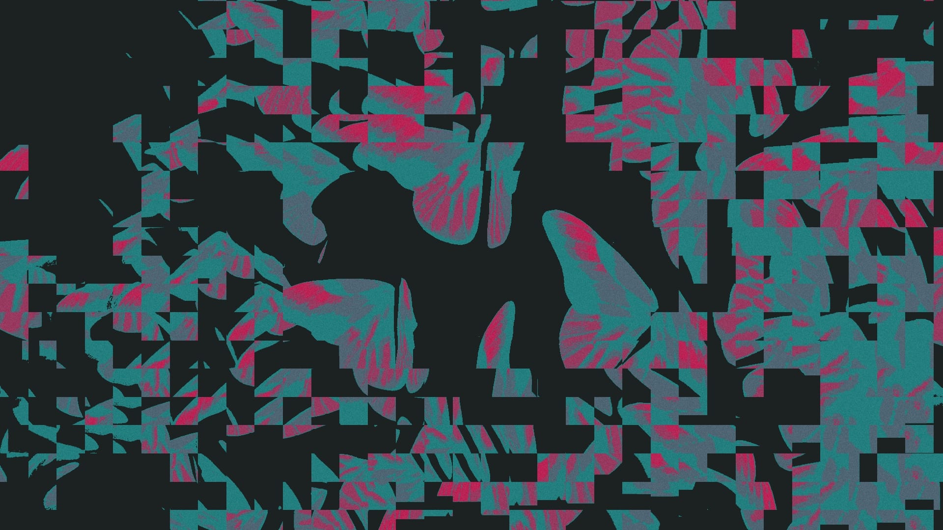
I wanted the invite to the concert to be special and include a poster for the event. I ended up with a design that was incomplete. It was incomplete, because everybody who was invited was tasked with coloring it in themselves, much like a coloring book. And the best part is: The wing of the butterfly prominent on the top right, is the exact shape as the wings of the butterflies that i was building. And I added four ArUco markers around the wing to make it easier for me to automate the tracking and perspective correction of the wing.
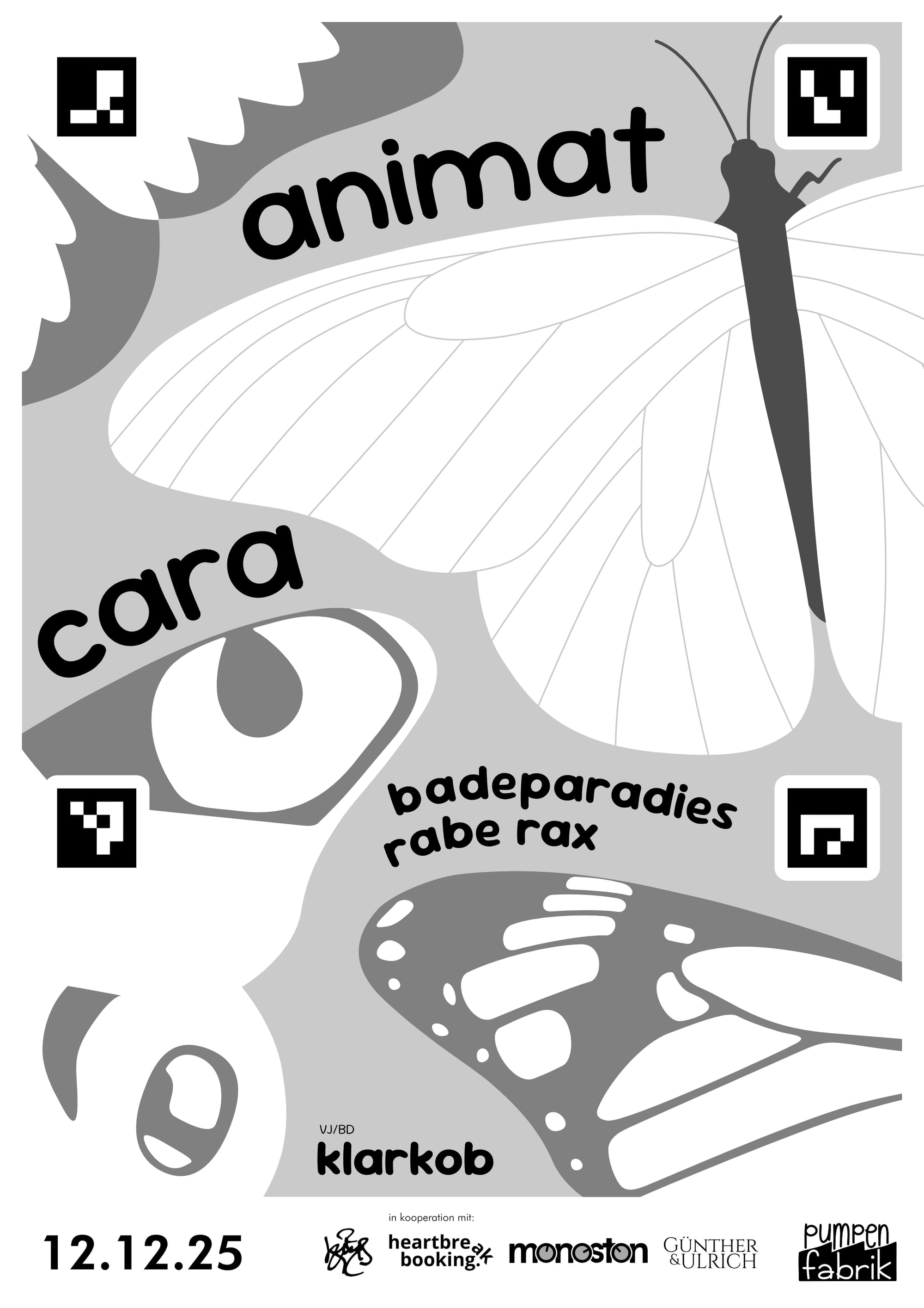

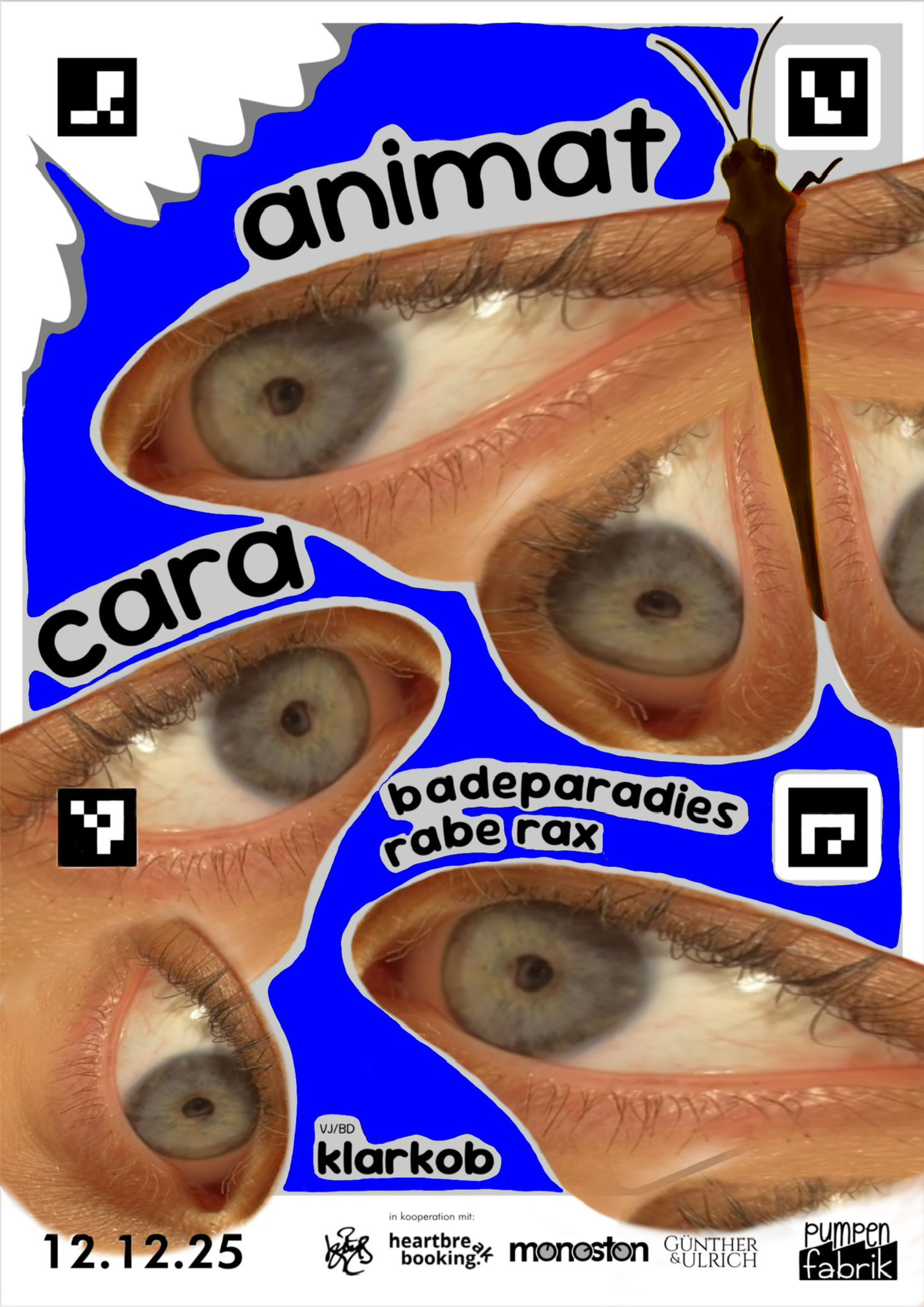
Blank invite I sent out (left), colored in by a child (middle), digital edit by Joanna (right)
Because this was more of a sidequest and in the end there just wasn't enough time, only a few notable entries made it in for the concert. For example one friend took some printouts with her to Daycare and had kids color them in.
Render of Daycare Butterflies

[Projection Mapping & Movement]
My TouchDesigner project is structured into two parts. The scene component, which generates the wing textures and movement vectors and the rendering component, which takes all the scene outputs and renders each wing from the correct perspective relative to the projector.
Calibration
But how does TouchDesigner know where each butterfly is? Clearly I had to come up with a good system for calibration since I had to repeat it 48 times. Because time was limited I decided to constrain all butterflies to be positioned on a plane. This simplified things a lot, because it meant i only had to find the x and y coordinate as well as rotation for each butterfly.
Of course I still had to figure out the orientation of the plane. For this I could however just use the Tool camSchnapper in TouchDesigner. It is very handy for matching a virtual camera perspective to a real life projection. As a proxy geometry I used a simple subdivided rectangle and measured out six points with the same proportions on my backdrop.
The last thing on my list i had to calibrate was the endpoints for each servo. While I moved all servos to the same orientation prior to the assembly, fine-tuning was still necessary.
So the final calibration routine looked like this:
- The current butterfly moves slightly to locate it
- The wing angle can be manually controlled to fine-tune both open and closed position
- A projection mapping mask can be moved along X, Y and rotation until it perfectly matches the shape of the current butterfly
Scenes
render (left) and real closeup (right)
The main task of the scenes component was to generate the wing textures and movement vectors.
The Scenes had a variety of inputs to use for interactivity. Most importantly they received a live audio feed from the mixer via Dante. This audio was analyzed in all scenes to enable audio reactivity. Other inputs included midi control from a control panel for adjusting a variety of parameters in each scene.
Because 3D Textures in TouchDesigner can't be animated, I used a custom Texture Atlas as the output format for the Scenes. Essentially its all the wing textures arranged in a grid as a single 2D Texture.
For the concert the scene component also outputted additional dmx signals to control all the other lights in the room.
Instancing
The instancing side is made up of two Geometry COMPs instancing the left and right wings respectively. There were a number of challenges here that I solved using a custom GLSL Texture.
The first challenge was the positioning, which was more difficult than anticipated. Because we have two transforms of the wing position the built in instancing tools weren't quite enough. The first transform is the general position which is determined during calibration. Importantly the rotation is pivoted at the center of the butterfly here. For this transform I used the built in instancing in the Geo COMP. The second transform is the variable angle of the wing which has a different pivot and was implemented in the GLSL Mat.
Next each wing had to be assigned with the correct texture from the Atlas. Because the Atlas only includes one texture per butterfly, the other side was mirrored. For the Geo COMP I used a simple Rectangle SOP with alpha to coverage transparency to achieve the shape.
And by default TouchDesigner renders the textures on both sides of the rectangle SOP. To have the back of each wing rendered solid black I added a condition to the pixel shader to check which way is facing the camera.